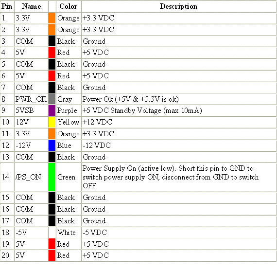
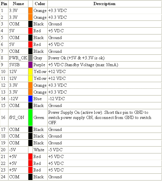
This page will eventually become a descriptive page about Computer Type Power Supplies. Till then it is home to a few images:


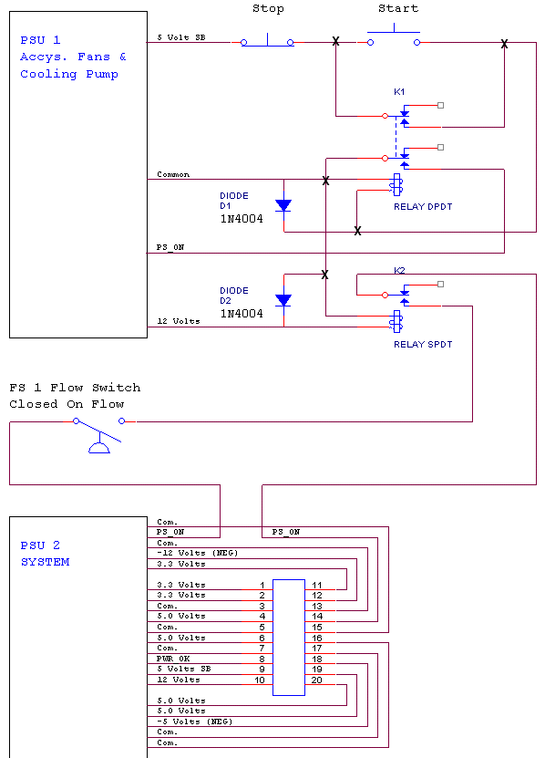
The below drawing illustrates how to couple two separate ATX form factor PSUs for what could be assorted applications. The idea being that one PSU would power a system while the other PSU could be used to power equipment such as fans, a water cooling pump, or other assorted accessories. A brief description is provided with the drawing.

A Dual PSU Configuration
In the above drawing PSU 1 is the auxiliary PSU. Unfortunately in getting the drawing to this page my junctions were lost. Thus a junction (connecting wires) is designated with a "X". PSU 1 has its own buttons to turn it on and off. To set up PSU 1 the main motherboard connector is removed as it is not used or required. Be it a 20 or 24 pin connector it is cut off as close to the connector as possible. The wires in any ATX form factor PSU are all color coded. See the examples at the top of this page. All like colors may be bundled together. That is all the Yellow (12 Volts) all the RED (5 Volts) all the orange (3.3 Volts) and all the Black (Common or Ground). Eventually it would be nice if I got some pictures in here!
So how does it work? A PSU turns on when a certain pin of the main connector is driven to a logic low (Common) by the motherboard. This pin is called PS_ON and is pin 14 on a 20 pin connector and pin 16 on a 24 pin connector. Matters not as this wire is always Green in color and should be the only Green wire in the connector. In the above circuit we are using what is called a "Latch" to take PS_ON low and keep it there. We are going to make use of what is called 5 Volt SB (Stand By) power. This 5 Volts is always present on the PSU whether the unit is on or off. This is always available on pin 9 and is always a Purple wire. Current from the 5 Volt SB is passed through a NC (Normally Closed) momentary pushbutton switch to a normally open pushbutton switch labeled Start. When the Start PB is pressed the current flows through the relay coil of K1 momentarily "pulling in" K1. This PB is also in parallel with a NO set of contacts on K1 which will close. The current flows to common and as a result of latching action K1 remains energized. Another set of contacts on K1 also are now closed. These contacts complete a path to common from the PS_ON of the PSU. The power supply PSU 1 is now energized and turned on.
Notice we are taking 12 Volts from PSU 1 to also turn on another relay labeled K2. On K2 another NO set of contacts closes as K2 is energized. These contacts are "in line" or "in series" with the PS_ON line of PSU 2. PSU 2 is connected normally to a motherboard in a computer. Everything about PSU 2 is normal with the exception of the PS_ON wire has been cut and a few things inserted in the line.
So what are we doing? We are "inhibiting" PSU 2 (the normal computer PSU) from turning on unless certain conditions are met. You will notice a Flow Switch in this path. Let's say we are running water cooling and using a 12 Volt pump. That pump is powered off PSU 1 (our Aux PSU). We want to not only make sure that PSU 1 is on and our pump energized but also that we have coolant flow. There is really no limit to what we can include in a permissive loop. When all the conditions we define are met, then and only then will our main computer PSU (PSU 2) be allowed to fire up and turn on our computer. Once running our computer will run as normal and allow a normal shutdown. However, all fans and water cooling will continue to run until we shutdown PSU 1 by simply pushing the Stop button. This allows for removal of excess heat after our computer is shutdown. Additionally if our water cooling were to fail (low or no flow) the system would do a hard shutdown. This sure beats the cost of replacing an expensive processor or processors.
About The Parts
The Start and Stop switches can be just about any generic momentary pushbutton switches. Start is a NO (Normally Open) and Stop is a NC (Normally Closed) switch. For the relays K1 and K2 I illustrated a DPDT (Double Pole Double Throw) and a SPDT (Single Pole Double Throw) relay respectively. Actually there is no need for Double Throw as we only care about contacts closing. However of some importance is that K1 uses a 5 Volt coil and K2 uses a 12 Volt coil. Just about any low current generic relays can be used, readily available from any electronic parts supplier. Two diodes are employed labeled D1 and D2. These are placed across the relay coils and serve to eliminate an inductive spike when the magnetic field of a relay coil collapses as the relay is de energized. Just about any common diode in the 1N4000 family will work. The entire circuit including relays could easily be mounted on some perforated board and placed in a 5 1/4" open bay with the pushbuttons available on the front panel.
I have omitted the line cord power connectors for the PSUs as well as many of the other connectors. The purpose at this point is simply to throw out a few ideas and thoughts.
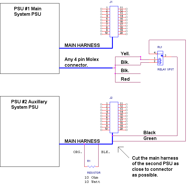
IMPORTANT: I also omitted placing a load of sorts on the 3.3 Volt bus of PSU 1. This practice is required on many early PSU when modding in this fashion. An ATX PSU is a switching type power supply and such power supplies like to see a load to regulate and function properly. Newer PSUs are less choosey however, a well heat sink 10 Ohm 10 Watt (or greater) resistor can be placed across the 3.3 Volt lines to common. I suggest a Google of PSU Modding for additional info.
I hope to get more done on this as time allows. For some great help and suggestions I suggest the MAXIMUM PC Magazine forums which can be found here:
http://www.maximumpc.com/forums/
Or the HL (Hardware Logic) forums which may be found here:
http://forums.hardwarelogic.com/
A Simple variation of the above.

Till Again
Ron