For those with an interest, myself and a forum friend (Manta) have embarked on a project to build a test station for the purpose of testing computer power supplies (PSU) outside the box. Today's power supplies are built to specifications, however power supply manufacturers are not actually held to compliance with any existing specification. The current PSU Design Guide may be found here. One of the problems with design guides is not just manufacturer compliance during the build but the fact the PSU market place and the demands placed on power supply units is evolving quicker than the specification. The provided link is not quite exciting reading. Matter of fact if you have trouble getting to sleep it is excellent reading material. Like most design guides it is rather boring reading, however, worth a look.
A little history behind this project. I always had an interest in ATX and BTX form factor power supplies as used in today's home computers. I always wondered if they could really deliver the advertised power they claimed. I also wondered if people actually understood how the information was presented. I had often given thought to the design and build of a PSU test bed or test bench. I have seen them in a few instances where through PSU testing was performed. Manta finally got me motivated enough to embark on this project. I suggested to Manta we design and build a small very basic demo version. Just a basic test box to see if this was something we really wanted to pursue. Following are a few pictures I exchanged with Manta during the initial build of a simple test box.
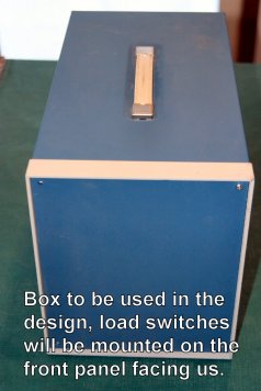
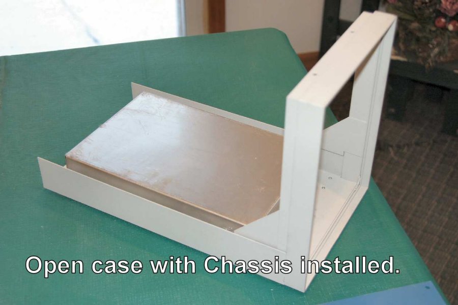
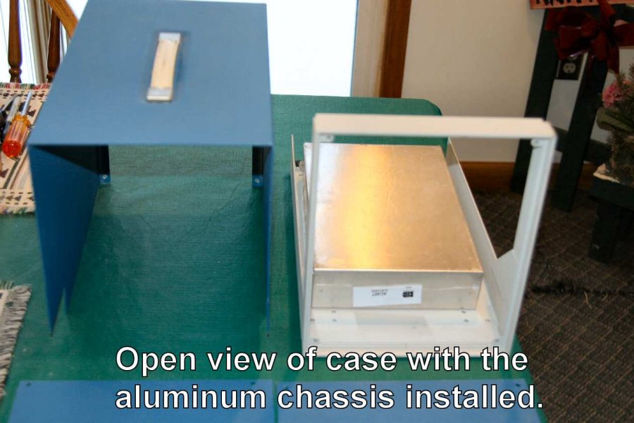
A simple workbox and chassis was chosen. Looked big enough at the time. Well looks can be deceiving!
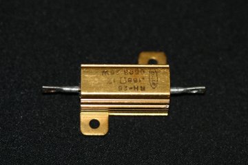 This
style will likely be used in a final build. Actually 3" Long in a 50 Watt size.
This
style will likely be used in a final build. Actually 3" Long in a 50 Watt size.
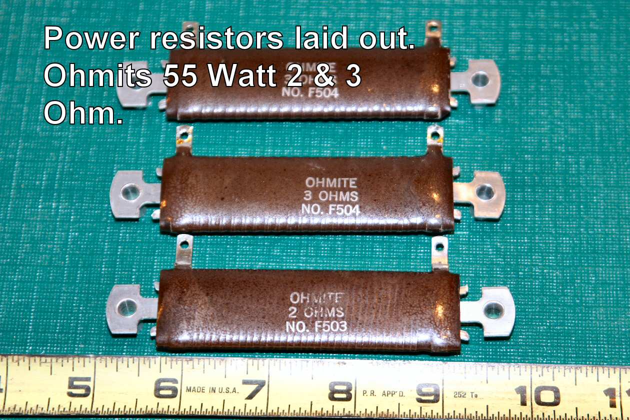
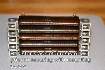
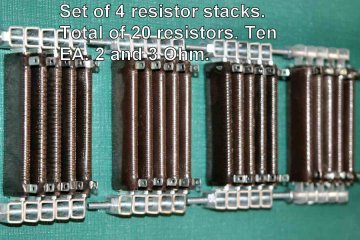
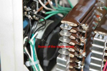
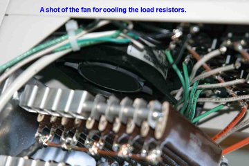
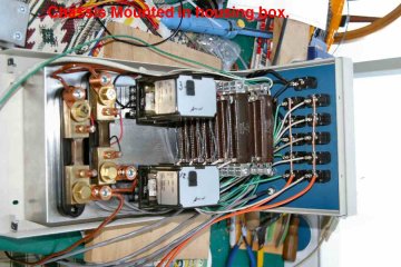
The resistors are the heart of any PSU test system. They will provide the necessary loads to simulate a running computer. This system will only look at two PSU voltage rails. We will look only at the 3.3 Volt and 12.0 Volt rails. A full test set would look at and evaluate all the rails of today's PSU systems. Additionally many resistors would be used for each rail. The resistors are stacked and spaced to allow airflow for cooling them and they do get hot! Again, remember, only two rails and what would be considered light current loads in our demo version. Power resistors can be expensive. They comprise a major part of the cost in a project like this.
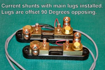
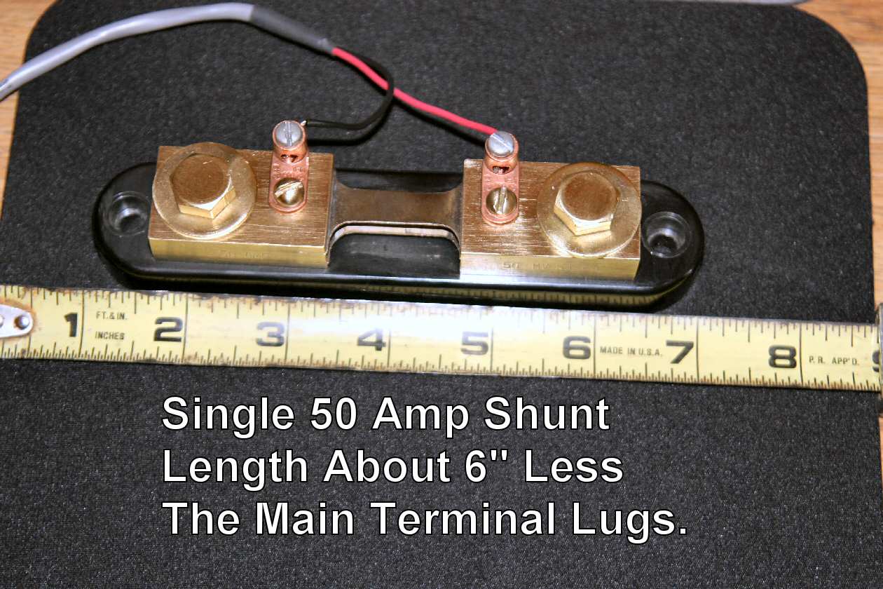
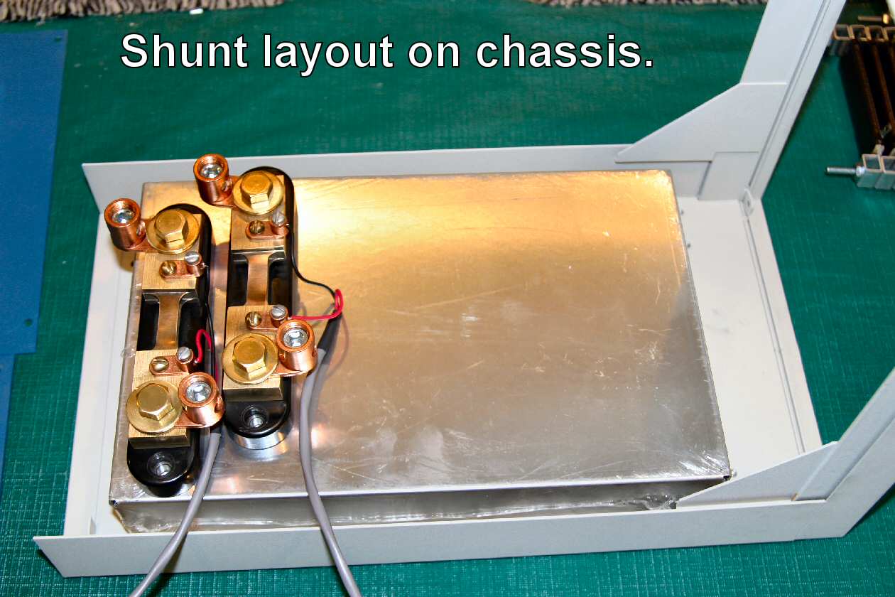
Above we have the current shunts. Each rail will have a shunt in an actual unit. Thus a need for 4 to 5 such devices. A current shunt is little more than a very low value resistor. Current passing through the shunt produces a small milli volt drop across the shunt. This small voltage is proportional to the current flowing through the shunt. The small inboard terminals are where the voltage is "picked off".
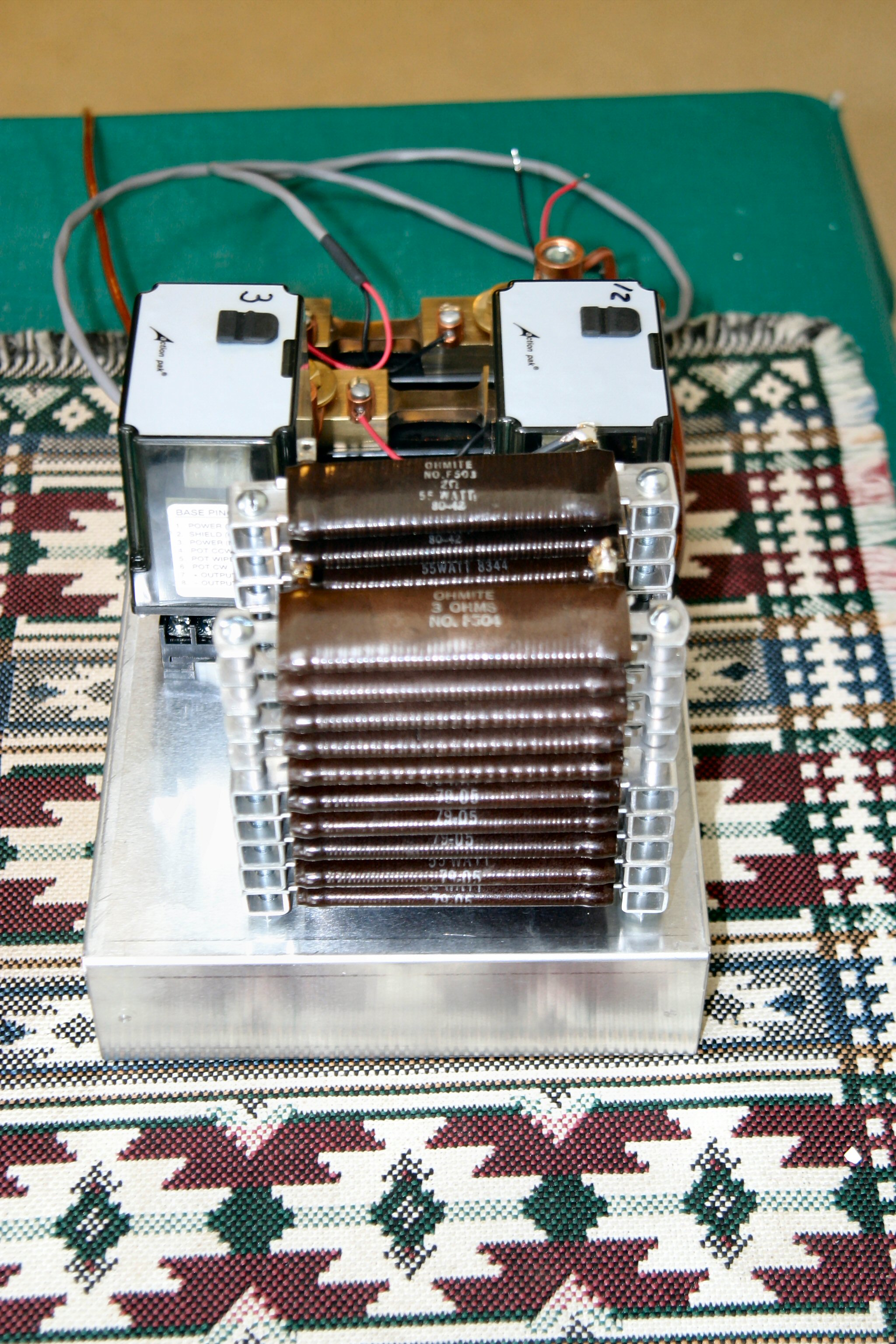
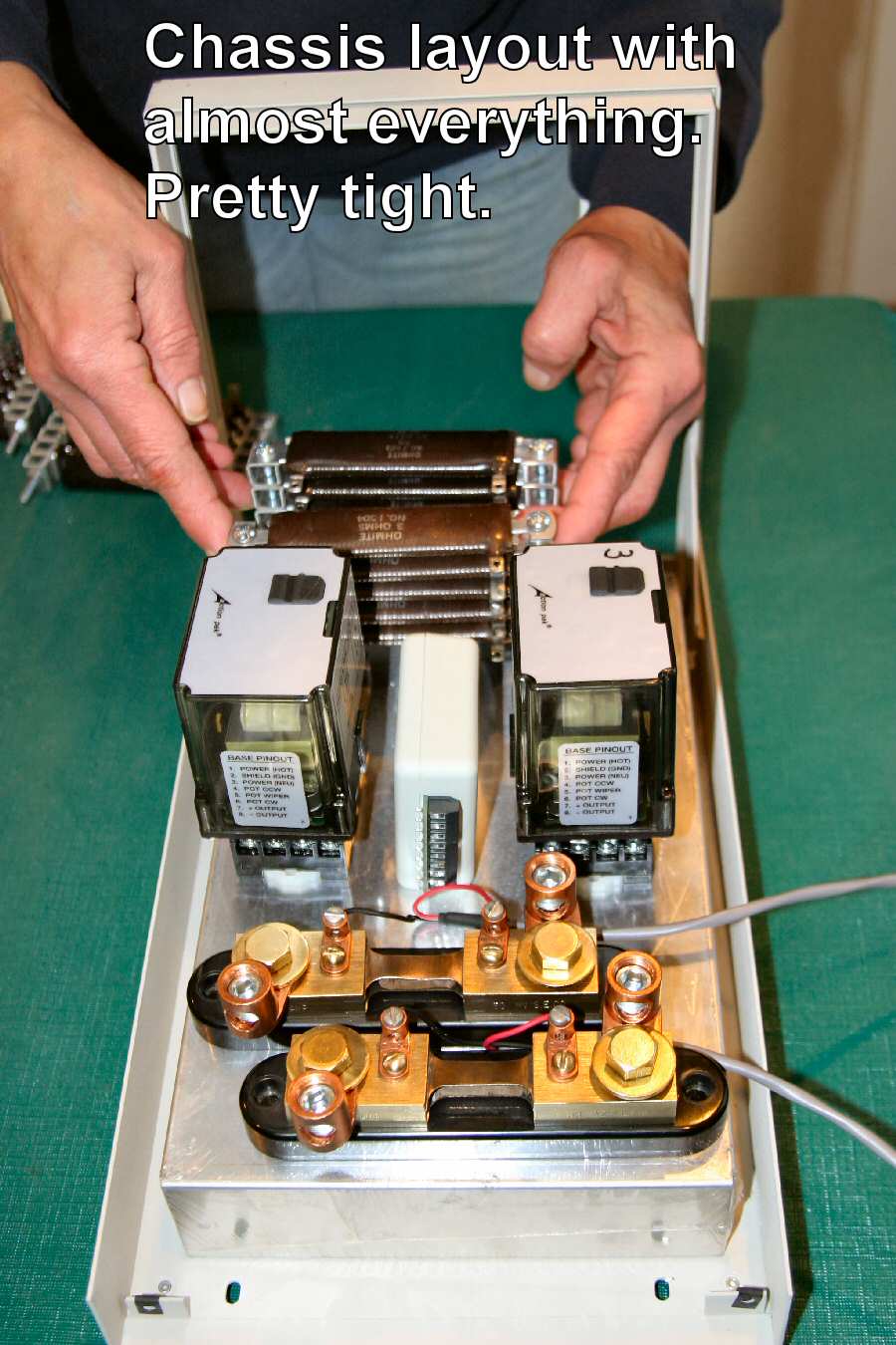
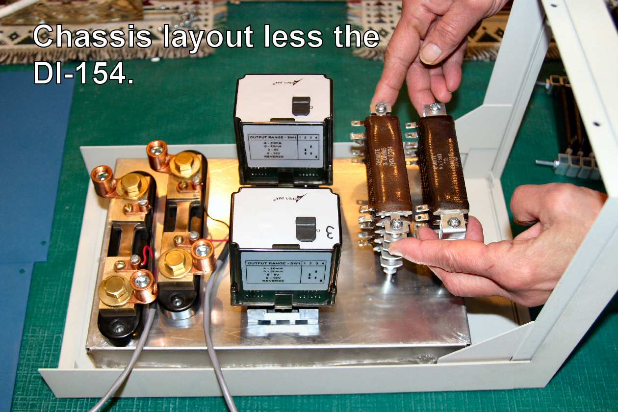
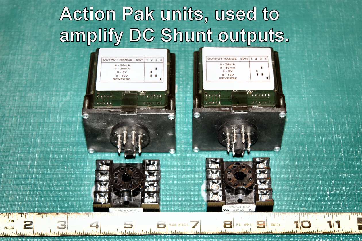
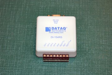
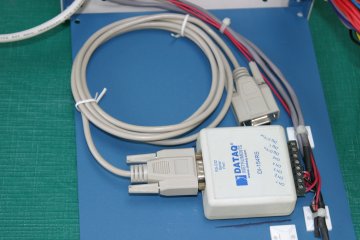
Things are going together. Due to the nature of the beast I used two DC amplifiers to amplify the shunt outputs. The system is to be software driven and an ADC (Analog to Digital Converter) used in a display. The ADC used in the demo version has only 4 channels and they are fixed at + / - 10 Volt inputs. The small milli volt outputs of the shunts would not read well without amplification.
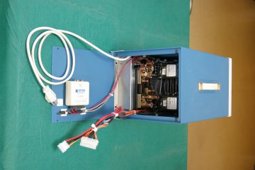
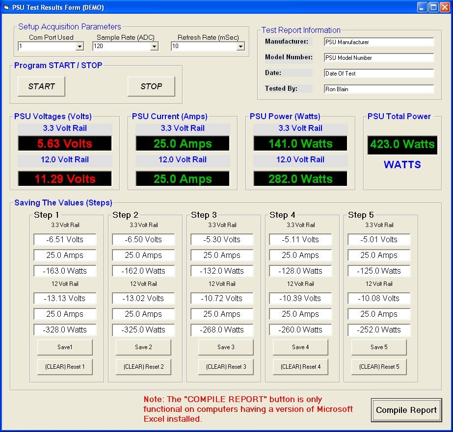
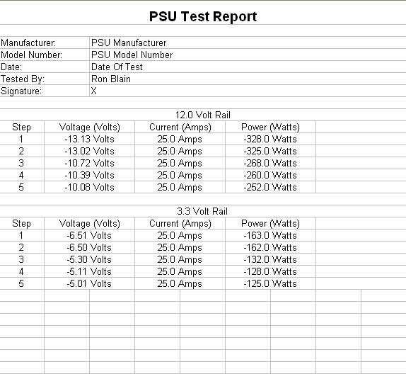
Finally things went together and the box was sent to Manta for some further test and evaluation. This web has several pages devoted to PSU items and there is a rough schematic on one of them. I believe it is the PSU test page. The following are a few screen shots of the software and a generated report. They are demo and were not run using the box as the box was gone when I decided to make them. Not too bright of me!
Non active old page.
Ron