Home Page
AR Page Cartridges Case Gauges Headspace Information Marlin Lever Guns Service Rifle Loadings
Downloads Page Chamber Test Loading Precision M1 Garands Powder Primers Sight Tools
Rimfire Images 10 Images 11 Images 12 Images 13 The 45 Page The Big Dig Scales M1A
Case
Temps
Don't Lose
Fan
Speed
A Little About Fans & Fan Speed Control
The subject of controlling fan speed in today's electronics presents ongoing challenges as today's systems employ more and more electronics in smaller and smaller spaces. More components packed into smaller spaces means a greater need to remove heat. Heat is a primary enemy of today's electronics. For well over a half of a century the simple fan has been a solution to removing excess heat from enclosures. Fans simply work well and get the job done. However even the simple fan can use improvements and we will take a look at some of the methods we can employ to make our fans used for cooling more efficient. We will take a look at ways we can control fan speed and some of the fans used to cool today's electronic systems with a focus on the home computer. Remember, this is about fans in general and not a review of any specific fan or brand name of fan. Several fans and pictures of fans will be used to illustrate the various means of controlling fan speed.
So why should we even bother to control fan speed, why not just let the fans run at full speed whenever power is applied?
Let's take a look at a very basic fan:
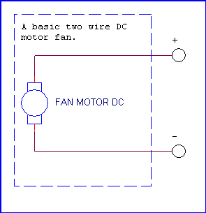
Not much to look at is it? A simple DC motor fan having two wires for power. We will assume it is a standard off the shelf 12 Volt DC fan. We apply 12 Volts with respect to polarity and the fan runs at its rated speed, we remove the power and the fan stops running. Laughing we could say we have a two speed fan as in on or off, nothing in the middle. :)
Since the fan is little more than a DC motor with blades to move air and since this is a simple DC motor if we vary the voltage we apply we can, to a point, vary the speed of the motor. Thus we can take a look at the simplest form of fan speed control:
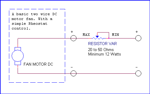
Here we have placed a variable resistor in series with our DC motor. As we change the resistance of the potentiometer (another name for our variable resistor) we will change the voltage applied to our load or in this case our fan motor. The change in voltage will in turn cause a change in the motor's rotational speed or fan speed. You will notice in the above little circuit we specify the value of the resistor to be 20 to 50 Ohms. Typically we would use the 20 Ohms for a fan application like the fan used on a CPU Heat Sink. Actually the values of the resistors used play an important roll. Fans have what we can call a stall speed. A fan rated for 12 Volts DC will eventually cease rotation as we move away from the nominal voltage. Later in this article we will explore the voltage needed to start a basic fan and the point where if we decrease voltage the fan stops rotating. I think we know that when a fan ceases rotation bad things can happen, especially a CPU cooling fan. :) The potentiometer allows us to change voltage in a linear fashion. There are other ways to do this which we will cover later.
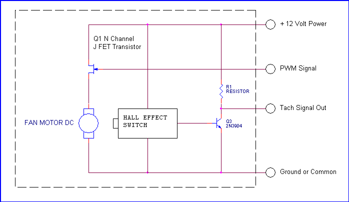
Most systems have evolved to using PWM (Pulse Width Modulation) as a means of fan speed control. PWM can be used with a two wire fan, however, is more popular with the newer three and four wire fans. Prior to moving into PWM lets take a look at a typical 3 wire fan circuit:
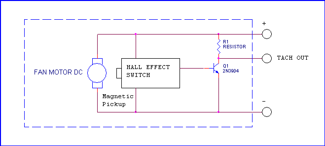
The above fan circuit differs from the basic two wire fan in that we have added an output signal and labeled it TACH OUT (Tachometer Output). The tachometer output can play a very important roll in fan circuits. A typical tachometer output signal is a pulse train or a series of pulses, the frequency of which is dependent on the rotational speed of the fan. Typically a fan will output 2 (Two) pulses per revolution. These pulses are generated by a small circuit embedded within the fan itself that generally consist of a small magnetic pickup commonly called a Hall Effect switch. The output of the Hall Effect switch will generally drive a small transistor designed to provide a pulse output.
NOTE: At this point it would be wise to point out the use of words like "approximately", "about", "typically" and "generally" are used quite often in the article. The article is written to provide the reader with an overview of various methods of fan speed control in a simple fashion. Something as simple as the tachometer output signal can be generated in a number of ways offering a variety of outputs. The focus here is basic home computer systems and electronics.
Note: I should also point out the basic drawings I use were created using a schematic design program called Orcad. I used existing "Parts Libraries" to represent approximately what the circuits would look like.
The tachometer output signal may have a few applications and uses. First it can provide the user with a visual indication of the fan speed and likewise provide the system with fan speed information. Additionally during cooling a lack of pulses from the fan tachometer is a good indication our fan has quit running thus not moving air and accordingly bad things can happen. The lack of pulses could for example trigger an alarm, including audible and visual alarms for a user or in critical applications trigger an automatic system shutdown. The tachometer output can also be used for precise fan speed control in what are known as "Closed Loop" applications.
Now we will look at a few graphical examples of PWM and get a working knowledge of the concept:

The image seen here and labeled 25% Duty Cycle is an illustration of PWM. The pulses in the example have a frequency of 30 Hz (Hertz) or 30 Cycles per second. The relationship between time and frequency is Time = 1 / Frequency and Frequency = 1/ Time. Therefore the time for a single cycle of a frequency of 30 Hz is 0.0333 seconds. Now in our 25% Duty Cycle illustration we can see our pulses have a an amplitude of 12 Volts. So what are we doing exactly with this PWM stuff? We are applying 12 Volt power to our load (a fan) for .00833 second then no power for .02497 second, and the cycle repeats. Needless to say for this brief Off period the fan continues to spin. We are "pulsing" our fan with power for the duration of the positive portion of our pulses. The "width" of our positive pulses determines the "on" time of our fan motor.
The remaining images depict pulses having pulse widths of 50% and 75% respectively. The end result of increasing the PW or Pulse Width is increased rotational speed of the fan. We should note that these are fixed examples. In reality the PW can be varied based on needed speed. We could for example have a small processor monitoring several temperatures in a system and supplying several fans. Depending on programming, that processor device could increase the positive pulse width to specific fans in a system to afford more cooling (air flow) as devices get hotter. More heat, more cooling while less heat, less cooling. We are only using power as needed and reducing the overall noise levels generated in our systems. This makes for all around more efficient cooling. Efficient always being a good thing. We will discuss some of these fan controller processor devices later in this article.
Now with the good comes some bad. I used an example of a frequency of 30 Hz. Actually 30 Hz. is typically used for what is known as Low Frequency PWM. 30 Hz. is also well within the human hearing range on the low end of the spectrum. With the fan constantly switched On & Off using low frequency PWM the fan may produce the PWM signal in an audible fashion.
 There is also another caveat to low frequency PWM. Looking back to our
illustration of our 3 wire fan with a tachometer output we can see that the
tachometer output will only be present when power is applied to the fan. Power
is only applied when our pulses are positive at 12 Volts. Therefore our output
pulses as speed will be chopped up a little. The results will look a little like
this:
There is also another caveat to low frequency PWM. Looking back to our
illustration of our 3 wire fan with a tachometer output we can see that the
tachometer output will only be present when power is applied to the fan. Power
is only applied when our pulses are positive at 12 Volts. Therefore our output
pulses as speed will be chopped up a little. The results will look a little like
this:
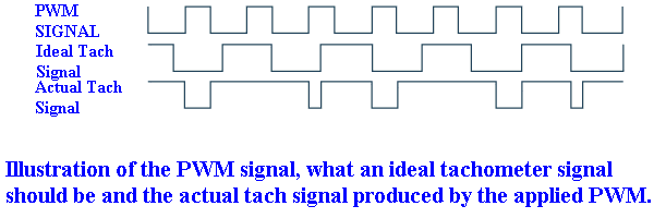
We want to note the difference between our ideal and actual tachometer signals. There is a workaround for this problem. Lets look at the following illustration:

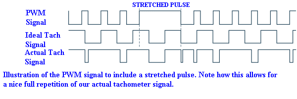
What we have done to improve our PWM signal is include an occasional "Stretched Pulse" and what this does is allow the On Time of our fan to output an occasional well defined tachometer output pulse to our system.
Now a little about these Tachometer Output Pulses. Remember how we mentioned earlier that a single revolution of our fan would produce two pulses? That alone really says little for the average user. Things are not well enough defined at this point. We need to get things to a common engineering unit, something like RPM (Revolutions Per Min.) would be nice. Therefore lets say purely as an example our fan returns two pulses in one second. Since two pulses equal one revolution we could therefore say we have one revolution per second or 60 RPM. Not many fans I am aware of turn or rotate at 60 RPM but you get the idea.
Interesting enough, as I write this I am looking at a running computer. The system has two 80mm fans for rear exhaust. Each fan has Light Emitting Diodes. On the upper fan the LEDs produce a constant glow. That fan is connected to a straight 12 Volts. However, the lower fan is connected to a PWM signal. The LEDs pulsate and interesting enough they seem to fire rapidly maybe 10 times then a slow noticeable On time occurs longer than the other pulses. This would be that "Stretched Pulse" we mentioned. Later in this article we will take a better look at this. Maybe capture a few PWM images on an oscilloscope and get some actual pictures.
Thus far we have looked at our basic two wire fan and a three wire fan. We have looked at some of the pros and cons of each when used with both powered from straight DC, variable DC and PWM. Next we will take a look at the latest design for fans and that would be the Four Wire fan.
This design is interesting in that it allows us to power the fan with a constant supply of 12 Volts DC. This 12 Volts constantly applies power to out tachometer output circuit. Therefore our PWM input to the fan will not require a stretched pulse in our PWM pulse train. There is another benefit to a 4 wire fan not seen in the illustration. We can now make a transition from Low Frequency PWM to High Frequency PWM. We defined Low Frequency PWM as a frequency of about 30 Hz (30 cycles per second). High Frequency PWM has a target frequency of 25 kHz or about 25,000 cycles per second. Notice how the frequency has increased from the bottom range of human hearing to extending above the top of the human hearing range (20 kHz). The nice people over at Intel® actually wrote an entire specification devoted to 4-Wire Pulse Width Modulation (PWM) Controlled Fans. That specification may be found HERE. To read the specification just click on the HERE link. At this writing I do not have a four wire fan to use as an exhibit or for experimentation. However, let's look at and power up a few fans and take a few measurements.
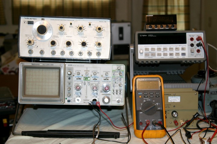
The equipment to be used consist of a scope to actually see a few signals, a good bench type DMM (Digital Multi Meter) as well as a small hand held DMM, some assorted power supplies to function as a source of power and a tachometer to read the speed of our fans. Unfortunately I am limited to space and a good work area due to home renovations. Everything is squeezed onto an ancient card table. The scope is an old Tektronix Model 2235 (ANUSM 488) analog oscilloscope with features I like for this sort of test. The downside of this 20 plus year old scope is there is no capability to take digital screen shots so we rely on a camera. For what we will look at this will be fine. We are using two DMMs to view our data. The bench type Agilent (HP) 34401A to look at Voltage and a Fluke 87 Handheld to look at current. The device on top of the scope is an old Wavetek Model 145 Function Generator which we will later use to generate some PWM signals. That Wavetek. though at maybe 30 years old and lacking nice digital features is still a hacker and at $5.00 at a garage sale was a steal for my home lab setup.
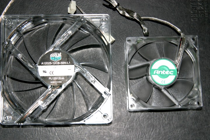
The fans we will be using are a pair of everyday generic fans, we have one 80 mm and one 120 mm fan. Both are 3 wire configurations. The first fan we will run is the 80 mm and we will run it just varying the DC Voltage applied. The PWM will come later. We will apply voltages of 12, 9, 6 and 3 Volts. I actually got a little surprise here in that I assumed (quite wrongly) that a 12 Volt fan would stall at 7 volts! The 80 mm fan ran as low as 3 Volts with the LEDs still glowing. WE will not take a picture for each voltage, however will make a table of what was going on.
Lets look at what we have with 12.078 Volts applied to our 80 mm fan:
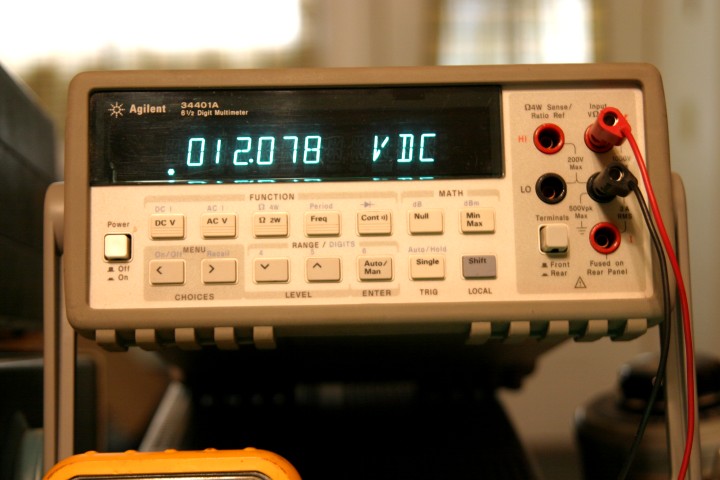
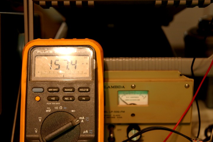
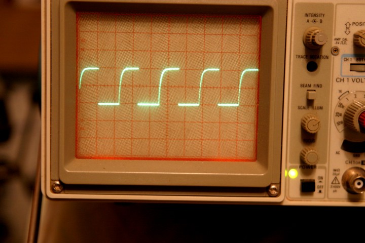
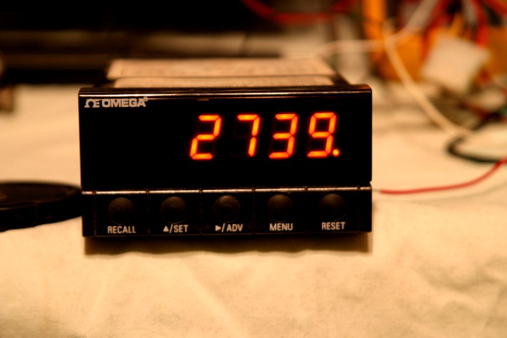
We can see with 12 Volts applied our fan speed is about 2,739 RPM and the fan is drawing about 157 mA of current (0.157 Amp). The scope shows the tachometer pulses being measured by our tachometer. Sorry about the flash bounce on our current meter. Now lets look at a table I made based on subsequent data:
| VOLTAGE APPLIED (VOLTS) |
CURRENT DRAW (mA) |
FAN SPEED (RPM) |
| 12.078 | 157.4 | 2,739 |
| 9.013 | 115.2 | 2,139 |
| 6.025 | 75.0 | 1,460 |
| 3.011 | 31.3 | 114 to 125 |
Note that at 3 Volts the fan output tachometer signal became very erratic. The scope image looked like this:
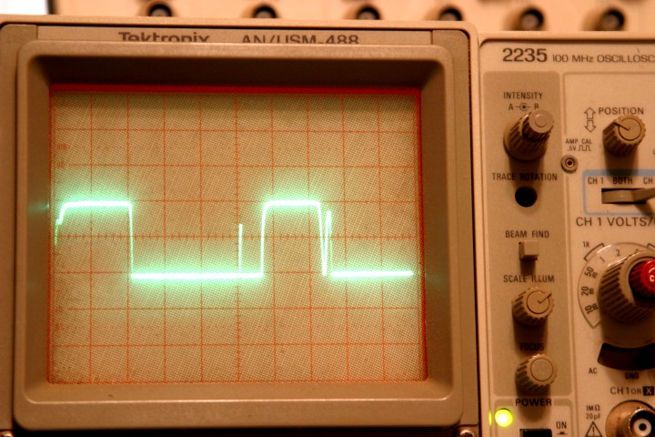 I intentionally increased the intensity (thus causing some "blooming") so the
extra spikes and pulses would be visible. The tachometer display was erratic and
actually would fluctuate more than I list as 114 to 125 RPM. Reducing the
voltage to about 2.5 Volts brought about a complete stall of the fan. Actually I
was surprised it ran at all even at 3 Volts. Increasing the voltage to about 3.5
Volts was enough to get rotation to begin.
I intentionally increased the intensity (thus causing some "blooming") so the
extra spikes and pulses would be visible. The tachometer display was erratic and
actually would fluctuate more than I list as 114 to 125 RPM. Reducing the
voltage to about 2.5 Volts brought about a complete stall of the fan. Actually I
was surprised it ran at all even at 3 Volts. Increasing the voltage to about 3.5
Volts was enough to get rotation to begin.

The 80 mm fan was one with LEDs having a Green color as can be seen. Interesting was that the LEDs continued to glow with the voltage reduced to 3.0 Volts. Granted a dim glow but none the less the LEDs sustained enough forward bias to glow.
The above control of fan speed is what we can expect to see when we apply a voltage change to a fan. We can see that the change in speed is not directly proportional to voltage change and is not linear.
This is an old page and actually no longer an active page in the web.
Today is Saturday 05 January 2008.
Ron